A colleague had his arm twisted for a Scrapheap Challenge-type project and had earmarked a distressed Kawasaki 440 engine as the project’s powerplant. Could I look over the engine for him? You bet!
The engine had previously been removed from the donor bike and was of unknown history. When I finally got it on my workbench I was a little dismayed to find it had both spark plugs removed and didn’t want to turn over. Oh well, in for a penny, in for a pound as they say….
Picture one: It was obvious this engine had covered some considerable mileage. It was deeply caked in grease and road muck and my first task was to clean as much of the crud off as possible. An hour spent with an assortment of paint brushes, old tooth brushes and paraffin began to reveal a recognisable engine and the stripdown could begin.
 Picture two: Kawasaki’s Z440 engine follows conventional Japanese twin cylinder engine design in that it has a 360 degree firing angle (both pistons rising and falling together) and a single overhead camshaft driven by a central chain. Less conventionally, it has a chain primary drive, which in effect means the engine runs ‘backwards’ and has a system of balance-weights in the crankcase designed to counter the effects of vibration. I started the strip by removing this breather cover from the top of the rocker box.
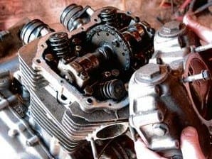
Picture three: Next the rocker box itself can be removed. Slackening the bolts in sequence allows the cover to be lifted off the top of the engine, revealing the camshaft and tops of the four valves. I took the precaution of loosening the rocker inspection caps first, as this will be difficult later.
Picture four: The rocker box carries the four rocker arms on their captive pivot pins. I’ll strip these for a closer examination later but most wear usually takes place on the cam followers as they skid over the cam lobes. There’s no apparent signs of scuffing on these, which bodes well for the rest of the engine. Note the tacho drive gear offset to the right.
Picture five: Before I can remove the camshaft I have to release the camchain tensioner to get lots of slack in the chain. Because the Z440 engine runs backwards (i.e. the crank rotates the opposite way to the back wheel), the tensioner is mounted on the front of the engine block instead of the usual place on the back. With the cap removed the tensioner unscrews from the block and I can withdraw the plunger and spring.
Picture six: To unscrew the two bolts holding the cam sprocket to the camshaft I’ll need to rotate the engine. A dummy nut mounted on the auto advance usually does the job, so at this stage I opt to remove the contact breaker backplate. The Z440 uses a ‘wasted spark’ ignition system, so only has one set of points. Marking the backplate first to aid re-assembly, I can now remove the three retaining screws and lift the backplate off.
 Picture seven: A good heave with a spanner on the dummy nut succeeds only in shearing off the auto advance drive pin; this engine is well and truly seized. I decide to fill the cylinders with penetrating oil and leave it for a few hours before proceeding. Hopefully I’ll be able to reclaim the drive pin later on.
Picture eight: After a suitable pause to let the penetrating oil work, I continue by removing the generator cover. This carries the alternator stator and I wrap it in rags to avoid any damage to the windings before laying it aside. Now I have access to the rotor bolt I can try to turn the engine with a socket on a long extension bar. Fortunately it frees off without too much drama and the engine turns over for the first time. It still feels a little rough though, and I’ll reserve judgement on the state of the engine internals until the barrels are off.
Picture nine: Returning to the top end I can now slacken and remove the two short 6mm bolts which hold the cam sprocket onto the camshaft. Before removing these completely I’ve taken the precaution of making a sketch of the timing marks on the sprocket. I have a workshop manual on the shelf but I always like to check timing marks before stripping an engine down just to make sure it goes back together the same way.
Picture 10: With the two bolts removed the cam sprocket can be dropped sideways off its mounting flange, leaving plenty of room to manoeuvre the camchain free. Unbolting and removing the three cam caps means I can now lift the camshaft out. The three cam caps are arrowed and must be replaced in the same positions, so I pop them back onto the head and wind their mounting bolts in by hand to make sure nothing gets lost or misplaced later. Each cap bolt has a dowel, make sure you don’t lose them down the camchain tunnel when lifting the caps off.
Picture 11: Before the head can be removed this external oil feed pipe has to be removed. Some Japanese engine designers chose to route the camshaft oil feeds up through the head bolts and through drillings in the cylinder head. Kawasaki, like Yamaha, tended to favour an external pipe like this one on their twins. The oil feed pipe mounts onto the oil pressure switch at the rear of the crankcase, which can also be removed at this stage.
 Picture 12: Now I can remove the eight main head nuts and lift off the cylinder head. The head nuts should be slackened off in sequence, working diagonally, and Kawasaki have helpfully cast in numbers alongside each nut to indicate the correct sequence. A sharp crack with a rubber mallet breaks the head gasket seal and I can lift the head off and put it to one side for attention later.
Picture 13: The barrels should now slide upwards off the pistons but are reluctant on this engine. Though I’ve succeeded in freeing it off, the piston rings have obviously corroded into the bores. At this stage I’m beginning to think we will have to re-bore the engine to make it serviceable, but careful work might yet mean I can salvage the bores and get away with just new rings. Gentle tapping with a rubber mallet eases the barrels slowly off the pistons until I can eventually lift them clear.
Picture 14: With the barrels off the extent of the damage to the pistons and rings is revealed. The rings have started to rust into the bores, almost undoubtedly because the engine had been left with its spark plugs removed, allowing in moisture. The rings have stuck into the piston grooves and I’ll spend some time with them later once I’ve evaluated the condition of the bores. The crud on top of the piston crowns would appear to be heavy carbon deposits, suggesting the engine was burning oil heavily before it was taken out of service. All worthy of note at this stage.
Picture 15: Removing the pistons is straightforward enough. With the outer circlip removed each gudgeon pin can be tapped through the small end until the piston can be lifted clear. As always, I’ve taken the precaution of marking the inside of each piston skirt with a reference mark, so if I do decide to re-use the pistons they can go back on the same rods. And I’ve also thrown away the old circlips to avoid any temptation to re-use them.
Picture 16: Next, the starter motor. Two small bolts hold the rectangular chrome cover in place. With these removed the starter itself can be released by removing two 6mm bolts which secure it onto the crankcase top. The motor drives the starter clutch via an endless single row chain. The chain drive sprocket simply slides off the splined shaft and I can pull the starter motor body sideways and upwards to release it. Finally I can hook the drive chain off over the generator rotor and store it away.
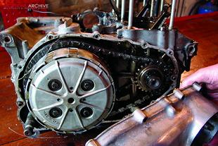
 Picture 17: Turning to the right side of the engine I can now remove the outer engine cover to reveal the clutch and primary drive. I always use an impact driver to remove cross-head casing screws, especially when they haven’t been disturbed for some time. Some of these screws showed evidence of previous damage but I’ll be replacing them with Allen screws on the rebuild anyway.
Picture 18: The primary chain is a heavy duty Hy-Vo item and is endless. To remove it the primary drive sprocket and clutch basket must be removed together. After removing the clutch pressure plate and friction plates I can take off this circlip which retains the clutch inner drum onto the gearbox input shaft. A similar circlip holds the primary drive gear onto the end of the crankshaft. Most designs use large nuts and locktabs, these circlips make this part of the job much easier.
Picture 19: Now I can lift the primary drive away as an assembly. The primary chain wears very slowly and has no tensioner as such, but runs over two nylon slipper blades bolted into the outer cover. Chains of this type can be very expensive to replace and I’m hoping it’s still within service limits.
Picture 20: Behind the clutch are the oil pump, the gear selector mechanism and kickstarter, all of which must be removed before splitting the crankcases. The oil pump is retained with four cross-head screws which free off easily after a crack with the impact driver. This oil pump has the word ‘ASCO’ stamped into its drive gear, which I don’t recall ever seeing on a bike before. I wonder if this could be an aftermarket oil pump of some kind and would be interested to know it’s origin?
Picture 21: Next, the gear selector. A small catch plate, retained by two screws, holds the selector shaft in position. With this catch plate removed the selector claws can be unhooked from the end of the drum and the whole shaft slid sideways out of the engine and set aside. This is the part you’d be replacing if you had damage to the splines retaining the gear lever. Finally the kickstarter mechanism can be turned and lifted clear after removal of its retaining circlip.
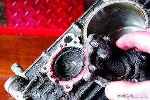
 Picture 22: Turning the engine over, I next remove this small cast housing which conceals a gauze strainer for the engine oil. This gauze strainer is frequently overlooked but should ideally be removed and cleaned at every major service. Encouragingly, this one shows little signs of debris in the engine oil despite the fact that it obviously hasn’t been disturbed for some considerable time.
Picture 23: Now I can split the crankcases. A number of bolts hold the two halves together, from both above and below, some of which can be easy to miss under caked-on grease. With all the bolts removed the lower crankcase should separate from the upper with a smart tap from the rubber mallet. Lifting the lower half clear reveals the two gearbox shafts and the crankshaft. It also reveals the alloy casting around the crank which carries the balancer weights.
Picture 24: Before removing the balancer weight housing I’m checking the timing marks on the weights themselves. These weights counter-balance the mass of the pistons and will have to be correctly timed on re-assembly. The weights are driven by a single row chain off the crankshaft, also a candidate for wear at high mileages. Interestingly, with the front bobweight correctly lined up to its timing mark. The rear bobweight looks slightly out, which may indicate a heavily worn balancer chain.
Picture 25: The crank itself runs in four shell-type main bearings, the two outers sandwiched between the crankcase halves and the inners located into the balancer mounting. With the balancer mounting finally removed I can lift out the crank. At this stage the generator rotor is still bolted onto the crankshaft. I didn’t have a satisfactory way of locking the engine to undo the bolt, so will clamp the crank into a vice to remove it later. The rotor could be left in place but has to be removed to get access to the starter clutch, which I will need to check for wear.
And that’s it for now. Next I need to sort through the pile of bits on the bench and carefully check everything for wear and damage before taking some decisions about how much we have to spend to make the engine serviceable. And decide who pays for the parts… ![]()


